ERGOMERA-125.AA Ultrasonic Heat Meter
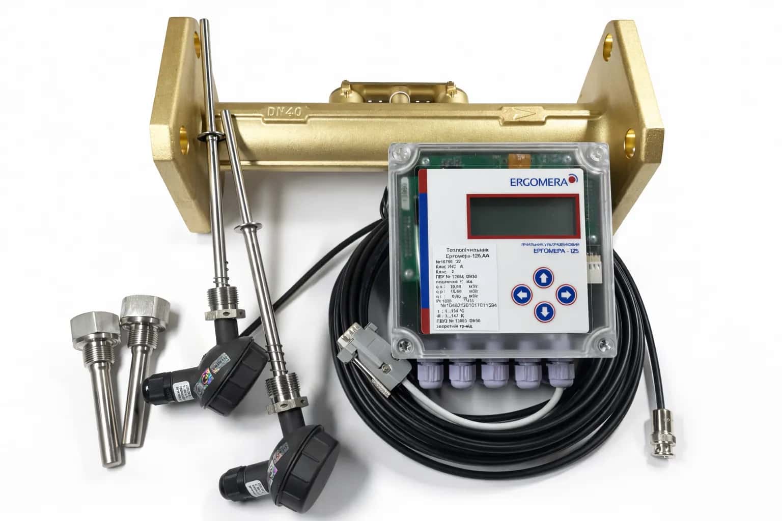
The ERGOMERA-125.AA heat meter is an ultrasonic, battery-powered instrument designed for commercial and process metering of thermal energy, heat carrier volume and mass, temperature, pressure and operating time in closed and open district heating systems. It is recommended for use in commercial heat metering stations, process monitoring of heat carrier parameters, supervision of district heating networks, heat substations, boiler houses, industrial facilities and domestic hot water systems. The meter is suitable for industrial and municipal facilities, as well as for building-level and apartment-level metering.
A manager will contact you to clarify the price and confirm the order.
PURPOSE & SPECIFICATIONS
Measured Parameters
Thermal energy consumed or supplied, heating and cooling energy, and thermal power
Volume and mass of water or heat-transfer fluid, as well as volumetric and mass flow rates
Temperature in the supply and return pipelines and the temperature difference
Gauge pressure in pipelines
Operating time and downtime
Key Advantages
Ultrasonic measurement technology — no moving parts and minimal mechanical wear
Accuracy class 2 in accordance with DSTU EN 1434
Autonomous power supply — up to 12 years of operation from the built-in battery
Optional two-channel version for complex metering configurations
Minimal pressure loss in the pipeline
Extensive data archives, including hourly, daily, monthly, process, alarm and intervention logs
Digital interfaces and standard communication protocols for easy integration with SCADA, AMR/AMI, monitoring and dispatch, and GIS systems
Automatic diagnostics and event logging
Ready for remote data transmission in near-real-time mode
Technical Specifications
Parameter | Value |
|---|---|
Type | ERGOMERA-125.AA |
Flow measurement method | Ultrasonic transit-time measurement |
Accuracy class | Class 2 according to DSTU EN 1434 |
Flow velocity range | 0.02–25 m/s |
Heat-transfer fluid temperature | 0.1–90 °C, optionally up to 280 °C |
Temperature difference range | 3–150 K |
Pressure rating | PN16 as standard; PN6, PN10, PN25, PN32 and PN40 available |
Power supply | Built-in 3.6 V battery; optional 230 V mains supply |
Data retention period | At least 12 years |
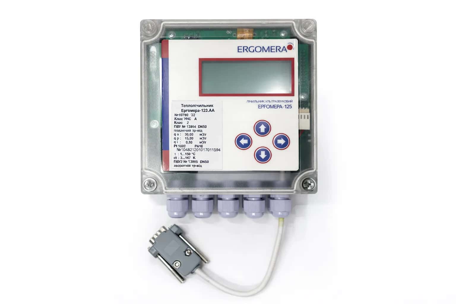
Display | 2 × 16-character LCD |
Enclosure protection | IP65; optionally IP68 |
Ultrasonic flow sensor protection | Up to IP68 |
Communication interfaces | RS-232 DB9 DCE; optional RS-485, Ethernet, M-Bus, Wireless M-Bus, LoRaWAN and NB-IoT |
Communication protocols | Modbus RTU/TCP, Ergo and M-Bus |
Pulse outputs | 2 |
Analogue outputs | Optional 4–20 mA |
Maximum cable route length | Up to 30 m; optionally up to 300 m |
Temperature sensors | Up to 3 Pt1000 sensors; optional Pt500 |
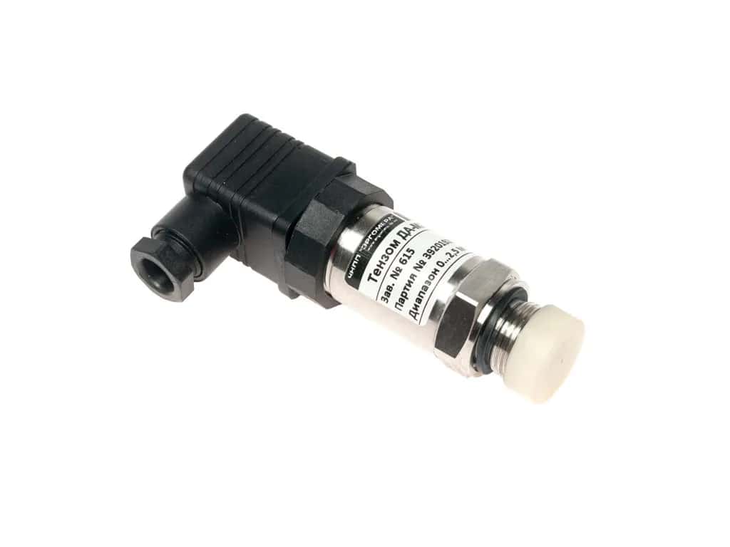
Pressure measurement channels | Up to 3 |
Data archives | 1,900 hourly, 365 daily, 44 monthly and 4,800 process records |
Design Versions
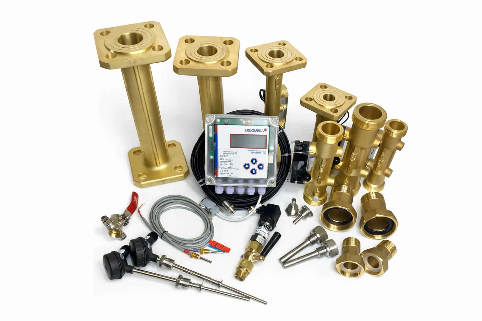
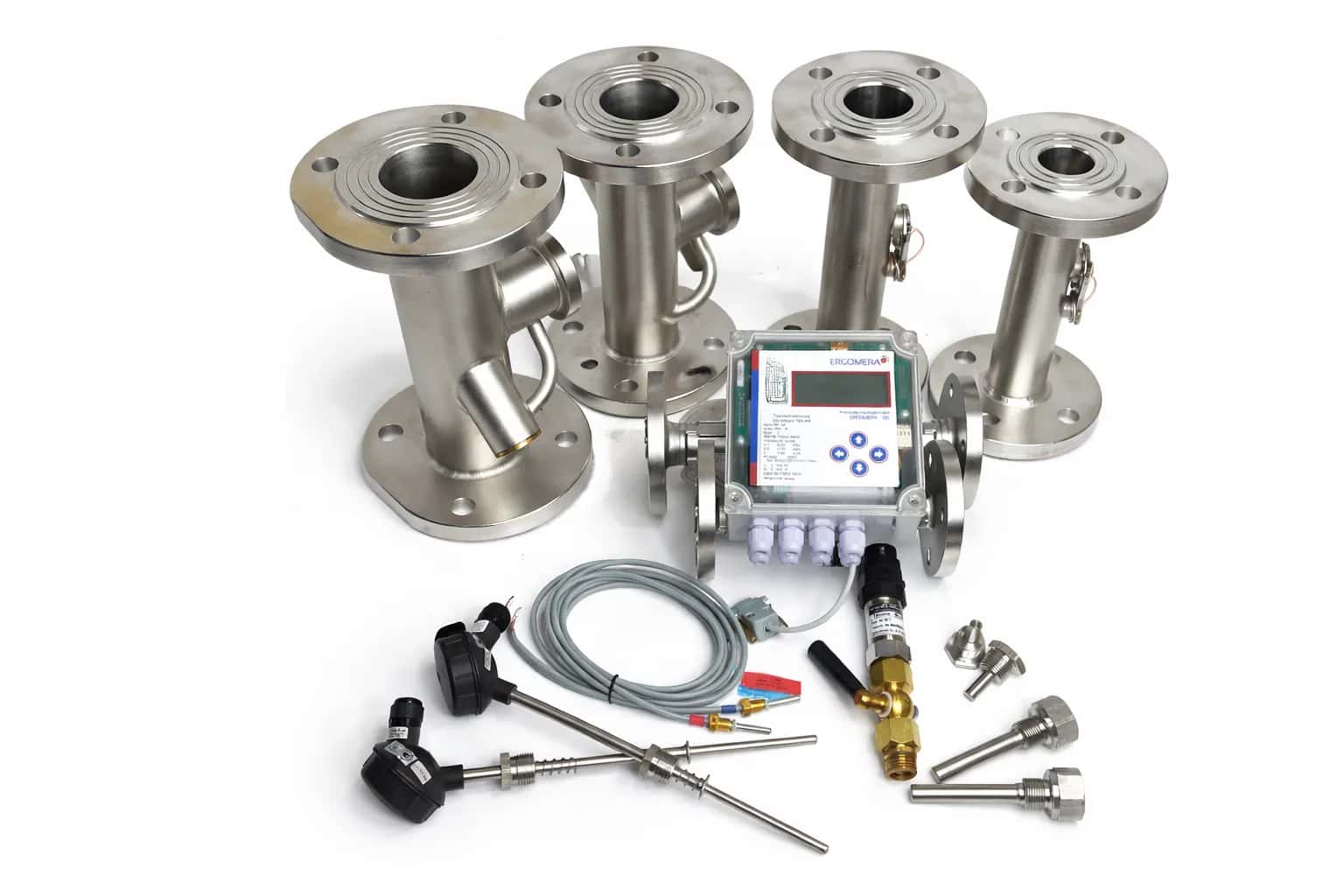
The ERGOMERA-125.AA heat meter is available with two primary ultrasonic flow sensor designs:
V1 — threaded, flanged or welded flow sensors in sizes from DN15 to DN500
V2 — insertion sensors for installation in an existing operating pipeline, available for DN250–DN500. A hot-tap version, V2-RShVS, allows installation without interrupting the flow.
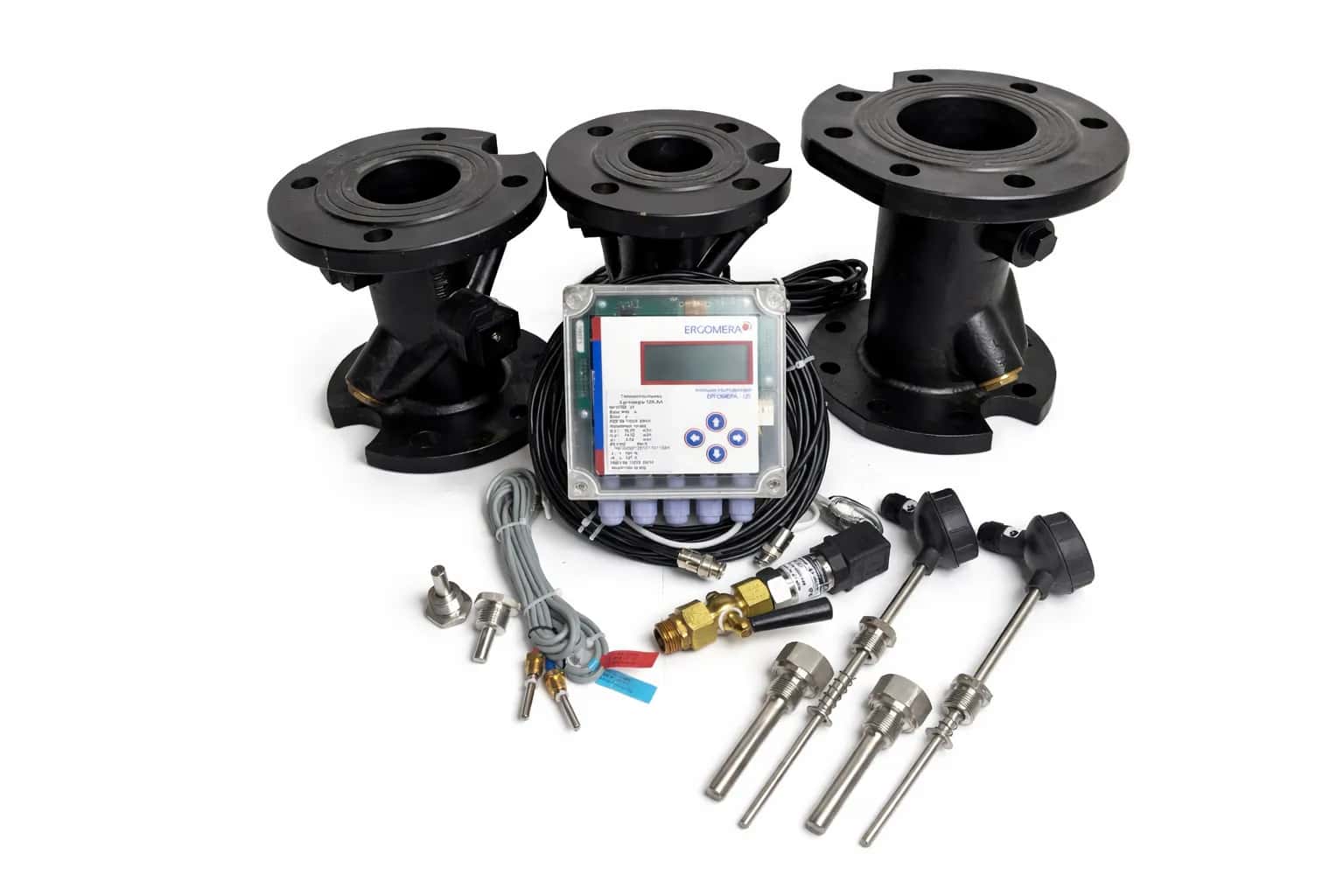
Available materials include brass, stainless steel, cast iron and Steel 20, optionally with a glass-enamel coating.
Metering Configurations
The meter supports a wide range of metering configurations, from basic single-channel arrangements to complex two-channel systems with cold-water monitoring.
Configuration | Description |
|---|---|
A1 | Single-channel configuration with the flow sensor installed in the supply pipeline |
A3 | Single-channel configuration with the flow sensor installed in the return pipeline |
A2 | Two-channel configuration with an additional control flow sensor in the return pipeline for leakage monitoring |
2A1 | Two independent heat supply systems, for example space heating and domestic hot water |
A4 / A4a | Configurations for heat supply sources using either measured or preset cold-water temperature |
A9 / A9a | Energy metering for a dead-end branch, such as a domestic hot water circuit or heat generation flow direction |
All configurations comply with DSTU EN 1434 and the applicable Ukrainian Technical Regulation for Measuring Instruments.
Applications
Combined heat and power plants and boiler houses
Central and individual heat substations
Industrial facilities
District heating networks
Building-level and apartment-level metering in apartment buildings, condominium associations and housing cooperatives
Rooftop boiler houses
Public and municipal buildings
Integration and Remote Monitoring
The ERGOMERA-125.AA can be easily integrated into existing metering, monitoring and dispatch systems.
Wired interfaces: RS-232, RS-485 and Ethernet
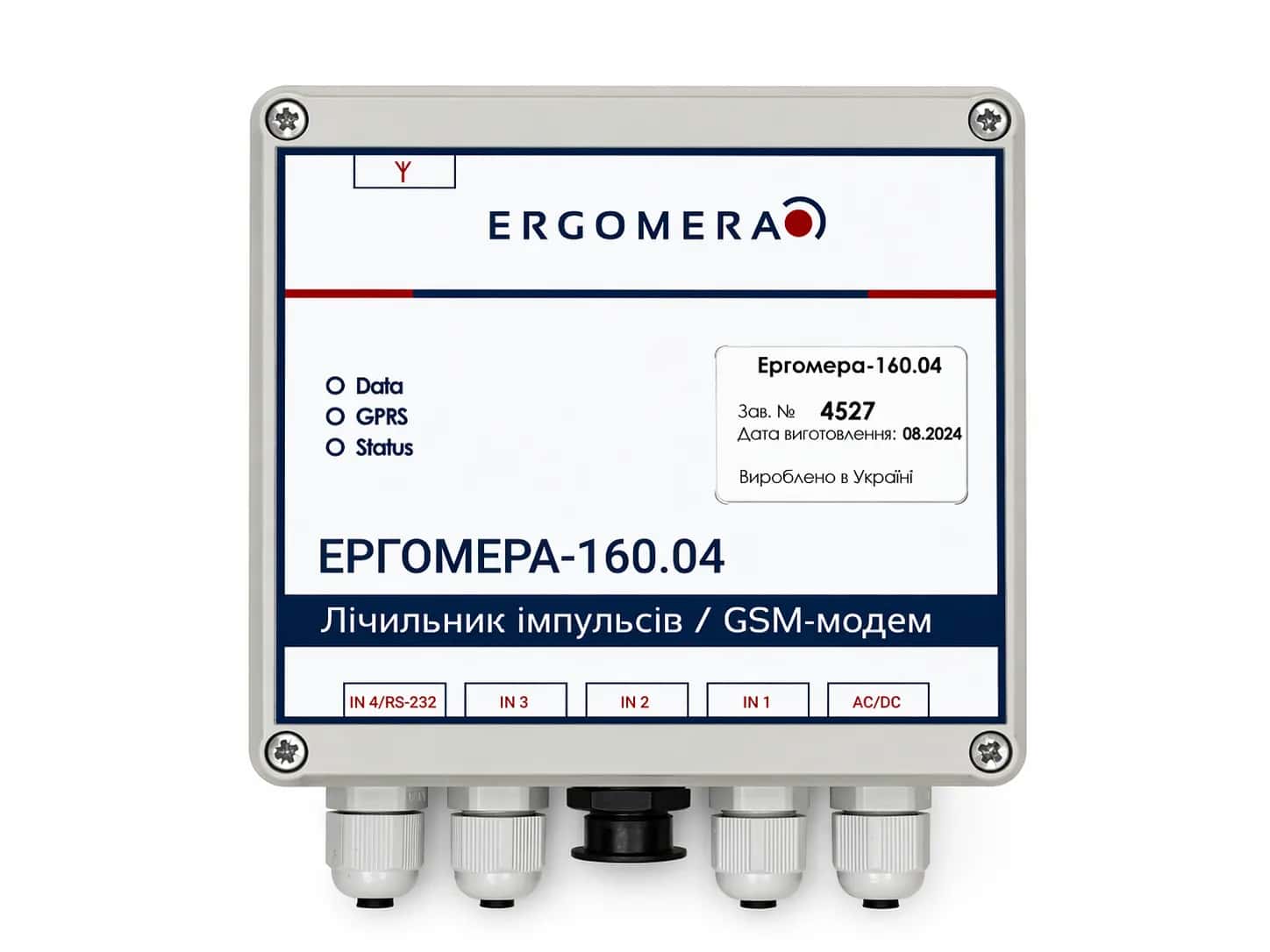
Wireless communication: LoRaWAN, Wireless M-Bus, NB-IoT and connection of GSM/GPRS modems
Protocols: Modbus RTU/TCP, M-Bus and Ergo
Automatic polling of instruments, data archiving and alarm notifications
Web interface and API for integration with SCADA, AMR/AMI, BMS, ERP and billing systems
The meter can operate as part of an integrated system combining thermal energy metering, additional cold- and hot-water metering channels, and Modbus RTU monitoring via RS-485.
Data Archiving and Processing
The instrument is equipped with non-volatile memory and supports long-term data storage:
Hourly archive — 1,900 records
Daily archive — 365 records
Monthly archive — 44 records
Process archive — 4,800 records
Alarm archive
Intervention archive
The following functions are supported:
Operating time recording
Downtime monitoring
Event logging
Alarm signalling
Near-real-time data transmission
Main Measurement Ranges
DN | Nominal flow rate qₚ, m³/h | Maximum flow rate qₛ, m³/h | Installation length L, mm |
|---|---|---|---|
15 | 1.5 | 1.9 | 110–190 |
20 | 2.5 | 3.1 | 130–190 |
25 | 3.5 | 4.3 | 160–260 |
32 | 6 | 7.5 | 180–260 |
40 | 10 | 20 | 300 |
50 | 15 | 30 | 270–300 |
65 | 25 | 50 | 300 |
80 | 40 | 80 | 300–350 |
100 | 60 | 120 | 350 |
125 | 100 | 200 | 350 |
150 | 150 | 300 | 500 |
200 | 250 | 500 | 500 |
250 | 400 | 800 | 600 |
The available product range extends up to DN600.
For sizes above DN250, the nominal flow rate is calculated as:
qₚ = 4,500πd²
The maximum flow rate is calculated as:
qₛ = 57,600πd²
where:
d is the internal pipeline diameter in metres.
Available Metering Configurations
ERGOMERA-125.AA heat meters can be ordered with the following metering configurations.
Configurations Complying with DSTU EN 1434
ERGOMERA-125.AA A1
Ultrasonic flow sensor installed in the supply pipeline.
ERGOMERA-125.AA A3
Ultrasonic flow sensor installed in the return pipeline.
ERGOMERA-125.AA A2
Ultrasonic flow sensor installed in the supply pipeline, with an additional control flow sensor installed in the return pipeline.
ERGOMERA-125.AA 2A1
Combination of two metering systems:
System 1 selected from the A1, A9 or A9a configurations
System 2 selected from the A1, A9 or A9a configurations
Configurations Complying with the Rules for Technical Operation of Heat-Generating Installations and Networks
These configurations comply with the Rules for Technical Operation of Heat-Generating Installations and Networks approved by Order No. 71 of the Ministry of Fuel and Energy of Ukraine dated 14 February 2007.
ERGOMERA-125.AA A4
Ultrasonic flow sensors installed in the supply and return pipelines, with an additional temperature sensor for measuring the cold-water temperature.
ERGOMERA-125.AA A4a
Ultrasonic flow sensors installed in the supply and return pipelines, with a preset constant used as the cold-water temperature.
ERGOMERA-125.AA A9
Designed for two separate heat supply systems using a measured cold-water temperature.
ERGOMERA-125.AA A9a
Designed for two separate heat supply systems using a preset cold-water temperature constant.
Comparison of Metering Configurations
Configuration | A1 | A3 | A2 | 2A1 | A4 | A4a | A9 | A9a |
|---|---|---|---|---|---|---|---|---|
Number of flow channels | 1 | 1 | 2 | 2 | 2 | 2 | 2 | 2 |
UFS No. 1 installed in the supply pipeline | + | – | + | + | + | + | + | + |
UFS No. 2 installed in the return pipeline | – | + | + | + | + | + | + | + |
Supply pipeline temperature sensor | + | + | + | + | + | + | + | + |
Return pipeline temperature sensor | + | + | + | + | + | + | + | + |
Cold-water temperature sensor | – | – | – | – | + | – | + | – |
Preset cold-water temperature constant | – | – | – | – | – | + | – | + |
Energy calculation based on UFS No. 2 | – | + | – | + | + | + | + | + |
Display of the difference between supply and return flow rates for leakage or water draw-off monitoring | – | – | + | – | + | + | – | – |
Functions Not Covered by the Measuring Instruments Technical Regulation
For each metering configuration, an additional cold- or hot-water meter with a pulse output can be connected, provided that the corresponding expansion option is ordered during manufacture.
This function is available for versions equipped with an RS-485 interface.
Integration Options
Parameter | Value |
|---|---|
Primary interface | RS-232, EIA/TIA-232, DB9 |
Additional interface | RS-485, EIA/TIA-485 |
Wireless interface | LoRaWAN |
Wireless interface | Wireless M-Bus |
Additional interfaces | USB, Ethernet, HART and NB-IoT |
Communication protocols | Modbus RTU, Modbus TCP, M-Bus, Ergo V1 and Ergo V2 |
Transmitted data | Current values and archived data |
Maximum communication speed | Up to 115,200 baud |
Standard communication speed | 9,600 baud |
Maximum RS-232 cable length | 25 m |
Event-triggered communication initiation | Yes |
Self-diagnostics | Yes |
Time synchronisation | Yes |
SCADA integration | Yes |
PLC integration | Yes |
Near-real-time operation | Yes |
Scope of Supply
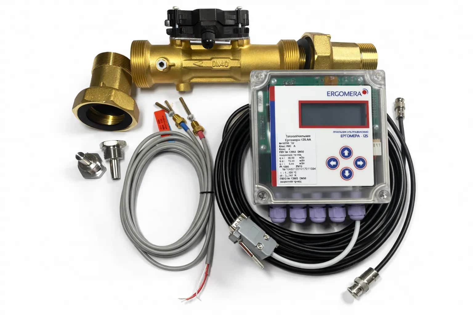
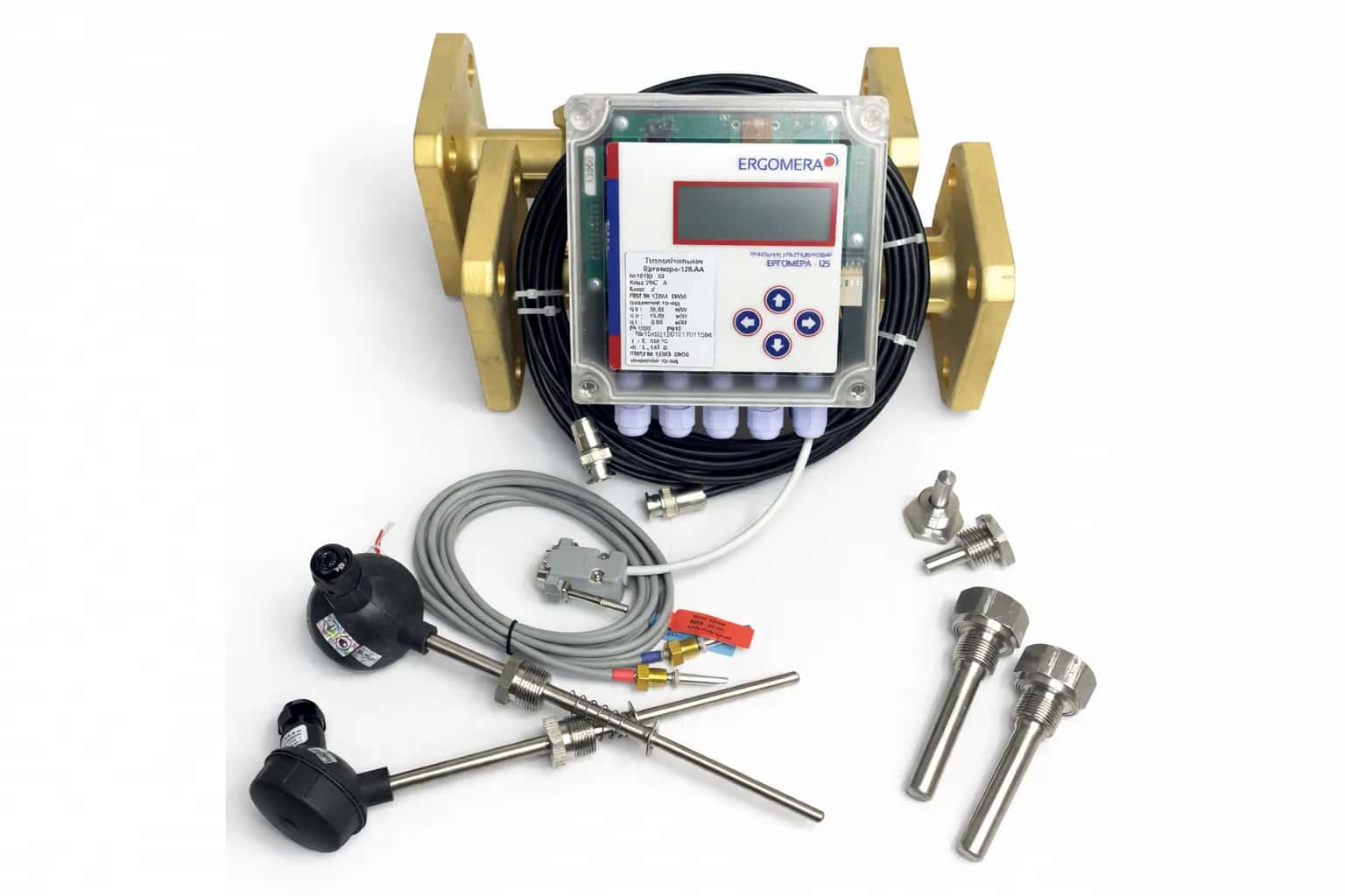
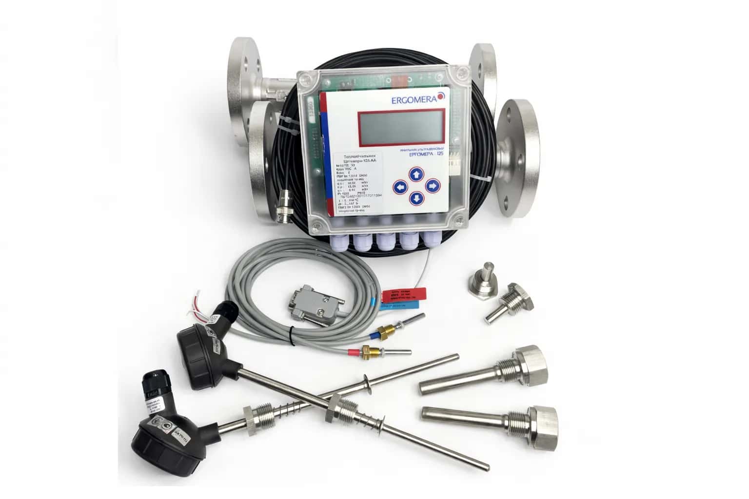
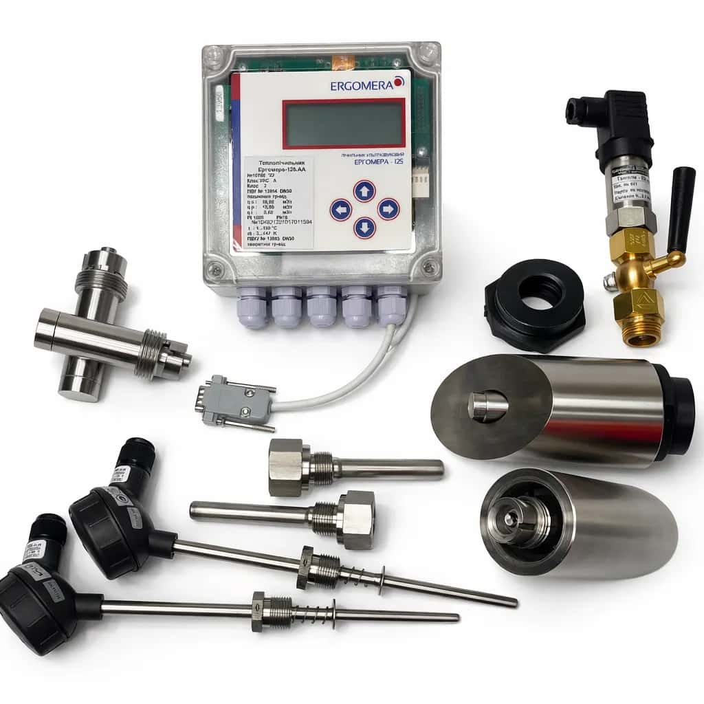
The standard scope of supply includes:
Measuring calculator — electronic processing unit
Ultrasonic flow sensors for the supply and/or return pipeline
Matched pair of Pt1000 temperature sensors
Connection cables
Product data sheet and installation and operating instructions
Optional equipment includes:
Additional temperature sensors
Pressure transmitters
Communication modems
Installation pipe sections
Expansion modules
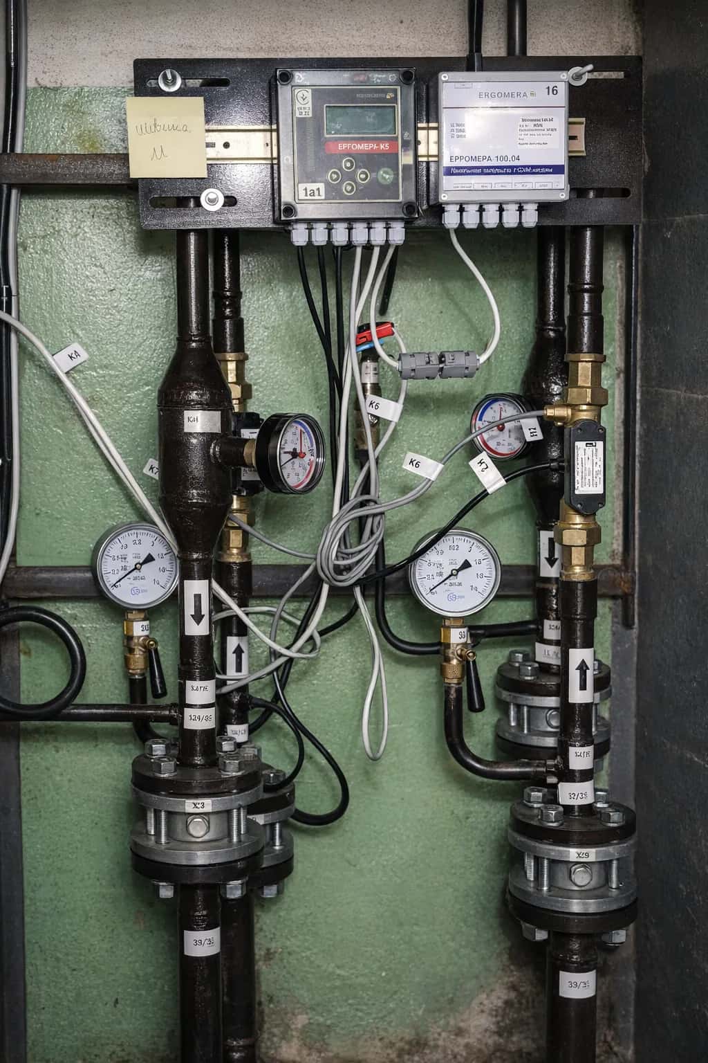
Installation
Installation should be performed by qualified and trained personnel in accordance with the IG-125/025 installation guidelines.
The meter supports both horizontal and vertical installation. For vertical installation, the heat-transfer fluid must flow upwards.
For most nominal sizes, straight pipeline sections upstream and downstream of the flow sensor are not required.
Verification and Warranty
The statutory verification interval is established in accordance with Order No. 1747 of the Ministry of Economic Development and Trade of Ukraine dated 13 October 2016.
Damage to or removal of the manufacturer’s seals constitutes formal grounds for refusal of warranty service and prohibits the use of the instrument for commercial metering.
Why Choose the ERGOMERA-125.AA
Manufactured in Ukraine with direct service support from ERGOMERA
Compliance with all applicable heat-metering regulations and standards
Ready for remote data transmission and digital monitoring
Minimal maintenance requirements, including battery replacement without breaking metrological seals
Open communication protocols and easy integration with third-party information systems
Related Products